华工正源中文站华工正源
- +86-27-87180102
-
社交媒体
 微信公众账号
 手机站
手机站
微信公众账号
手机站

| 产品模块: | 10G SFP+ ER Transceiver |
| 订购信息: | |
| 验证码: |
|
| 类 别: | 电子邮箱: | ||
| 电 话: | QQ: | ||
| *标题: | |||
| *留言内容: | |||
| *验证码: |
|
||
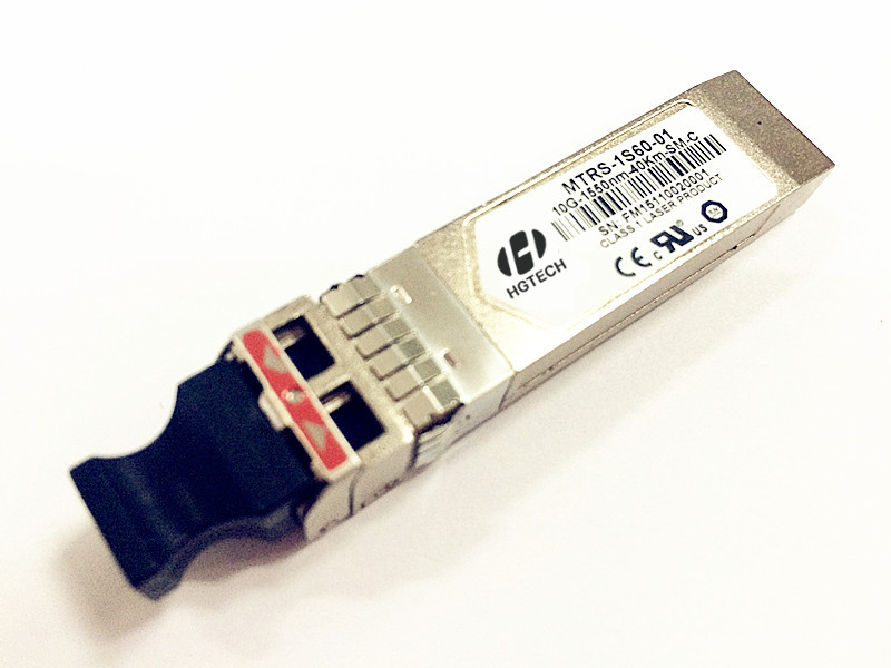
Description
MTRS-1S60-01 is a high performance, cost effective modules, which is supporting Multi Rate 1.25-11.3Gbps, and transmission distance up to 40km on SM fiber. The transceiver consists of two sections: The transmitter section incorporates a EML laser driver and a1550nm DFB laser. The receiver section consists of a PIN photodiode integrated with a transimpedance preamplifier (TIA) and a Limitting Amplifier. The module is hot pluggable into the 20-pin connector. The high-speed electrical interface is base on low voltage logic, with nominal 100 Ohms differential impedance and AC coupled in the module.
The optical output can be disabled by LVTTL logic high-level input of TX_DIS. Transmit Fault (Tx_Fault) is provided to indicate that the module transmitter has detected a fault condition related to laser operation or safety. Loss of signal (RX_LOS) output is provided to indicate the loss of an input optical signal of receiver. A serial EEPROM in the transceiver allows the user to access transceiver monitoring and configuration data via the 2-wire SFP Management Interface. This interface uses a single address, A0h, with a memory map divided into a lower and upper area. Basic digital diagnostic (DD) data is held in the lower area while specific data is held in a series of tables in the high memory area.
l Up to 40km transmission distance
l Support Multi Rate 1.25-11.3Gbps
l 1550nm cooled EML transmitter with TEC and PIN receiver
l SFI electrical interface
l 2-wire interface for integrated Digital Diagnostic monitoring
l SFP+ MSA package with duplex LC connector
l Hot pluggable
l Very low EMI and excellent ESD protection
l +3.3V power supply
l Power consumption less than 1.5W
l Operating case temperature: 0~+70°C
Applications
l 10GBASE-ER/EW
l 10GBASE-ER/EW + FEC
l 10G Storage system
l LTE optical repeater application
Specification
|
Absolute Maximum Ratings |
||||
|
Parameter |
Symbol |
Min. |
Max. |
Unit |
|
Storage Temperature |
TS |
-40 |
+85 |
℃ |
|
Supply Voltage |
VCC3 |
0 |
3.6 |
V |
|
Relative Humidity |
RH |
5 |
95 |
% |
|
RX Input Average Power |
Pmax |
- |
0 |
dBm |
|
Recommended Operating Conditions |
|||||
|
Parameter |
Symbol |
Min. |
Typical |
Max. |
Unit |
|
Operating Case Temperature |
TC |
0 |
25 |
70 |
℃ |
|
Power Supply Voltage |
VCC3 |
3.13 |
3.3 |
3.47 |
V |
|
ICC3 |
- |
350 |
450 |
mA |
|
|
Power Dissipation |
PD |
- |
- |
1.5 |
W |
|
Data Rate |
|
- |
10.3125 |
11.3 |
Gbps |
|
Transmission Distance |
|
- |
- |
40 |
Km |
Transmitter Operating Characteristic-Optical, Electrical |
||||||
|
Parameter |
Symbol |
Min. |
Typical |
Max. |
Unit |
Note
|
|
Center Wavelength |
λC |
1530 |
1550 |
1565 |
nm |
|
|
Side Mode Suppression Ratio |
SMSR |
30 |
- |
|
dBm |
|
|
Laser Off Power |
Poff |
- |
- |
-30 |
dBm |
|
|
Average Optical Power |
Pavg |
-3 |
- |
3 |
dBm |
|
|
Extinction Ratio |
ER |
6 |
- |
- |
dB |
|
|
Transmitter Dispersion Penalty |
TDP |
- |
- |
2 |
dB |
|
|
Relative Intensity Noise |
Rin |
- |
- |
-128 |
dB/Hz |
|
|
Optical Return Loss Tolerance |
|
21 |
- |
- |
dB |
|
|
Optical Eye Mask |
Compliant with IEEE 802.3ae |
|
||||
|
Single Ended Output Voltage Tolerance |
|
-0.3 |
- |
4 |
V |
|
|
Common mode Voltage Tolerance |
|
15 |
- |
- |
mV |
|
|
Tx Input Diff Voltage |
VI |
180 |
- |
700 |
mV |
|
|
Tx Fault |
VoL |
-0.3 |
- |
0.4 |
V |
At 0.7mA |
|
Data Dependent Input Jitter |
DDJ |
- |
- |
0.1 |
UI |
|
|
Data Input Total Jitter |
TJ |
- |
- |
0.28 |
UI |
|
|
Receiver Operating Characteristic-Optical, Electrical |
||||||
|
Parameter |
Symbol |
Min. |
Typ. |
Max. |
Unit |
Note
|
|
Center Wavelength |
λr |
1250 |
1550 |
1600 |
nm |
|
|
Receiver Sensitivity (Average Power) |
Psens |
- |
- |
-15.8 |
dBm |
1 |
|
Receiver Sensitivity (OMA) |
|
- |
- |
-14.1 |
dBm |
2 |
|
Stressed receiver sensitivity (OMA) |
|
|
|
-11.3 |
dBm |
2 |
|
Los Assert |
LosA |
-25 |
- |
- |
dBm |
|
|
Los Dessert |
LosD |
- |
- |
-16 |
dBm |
|
|
Los Hysteresis |
LosH |
0.5 |
- |
- |
dB |
|
|
Overload |
Pin |
-1 |
- |
- |
dBm |
1 |
|
Stressed Eye Jitter |
|
0.3 |
- |
- |
UIp-p |
2 |
|
Receive electrical 3dB upper cutoff frequency |
|
- |
- |
12.3 |
GHz |
|
|
Vertical Eye Closure Penalty |
|
2.7 |
- |
- |
dB |
3 |
|
Receiver Reflectance |
|
- |
- |
-26 |
dB |
|
|
Single Ended Output Voltage Tolerance |
|
-0.3 |
- |
4 |
V |
|
|
Rx Output Diff Voltage |
Vo |
300 |
- |
850 |
mV |
|
|
Rx Output Rise and Fall Time |
Tr/Tf |
30 |
- |
- |
ps |
20% to 80% |
|
Total Jitter |
TJ |
- |
- |
0.7 |
UI |
|
|
Deterministic Jitter |
DJ |
- |
- |
0.42 |
UI |
|
Notes:
[1] Average optical power shall be measured using the methods specified in TIA/EIA-455-95
[2] Receiver sensitivity is informative. Stressed receiver sensitivity shall be measured with conformance test signal for BER =1x 10-12 .
[3] Vertical eye closure penalty and stressed eye jitter are the test conditions for measuring stressed receiver sensitivity. They are not the required characteristic of the receiver.
|
Control and Status I/O Timing Characteristics |
||||||
|
Parameter |
Symbol |
Min. |
Max. |
Unit |
Note
|
|
|
TX Disable Assert Time |
t_off |
- |
10 |
µs |
Note1 |
|
|
TX Disable Negate Time |
t_on |
- |
1 |
ms |
Note2 |
|
|
Time to initialize including reset of TX_Fault |
t_init |
- |
300 |
ms |
Note3 |
|
|
TX Fault Assert Time |
t_fault |
- |
100 |
µs |
Note4 |
|
|
TX Disable to Reset |
t_reset |
10 |
- |
µs |
Note5 |
|
|
LOS Assert Time |
t_loss_on |
- |
100 |
µs |
Note6 |
|
|
LOS Deassert Time |
t_loss_off |
- |
100 |
µs |
Note7 |
|
|
Rate-Select Change Time |
t_ratesel |
- |
10 |
µs |
Note8 |
|
|
Serial ID Clock Rate |
f_serial_clock |
- |
100 |
kHz |
|
|
Notes:
[1] Time from rising edge of TX Disable to when the optical output falls below 10% of nominal
[2] Time from falling edge of TX Disable to when the modulated optical output rises above 90% of nominal
[3] From power on or negation of TX Fault using TX Disable
[4] Time from fault to TX fault on
[5] Time TX Disable must be held high to reset TX_fault
[6] Time from LOS state to RX LOS assert
[7] Time from non-LOS state to RX LOS deassert.
[8] Time from rising or falling edge of Rate Select input until receiver bandwidth is in conformance with appropriate specification
