华工正源中文站华工正源
- +86-27-87180102
-
社交媒体
 微信公众账号
 手机站
手机站
微信公众账号
手机站

| 产品模块: | 10G 10km SFP+ Transceiver |
| 订购信息: | |
| 验证码: |
|
| 类 别: | 电子邮箱: | ||
| 电 话: | QQ: | ||
| *标题: | |||
| *留言内容: | |||
| *验证码: |
|
||
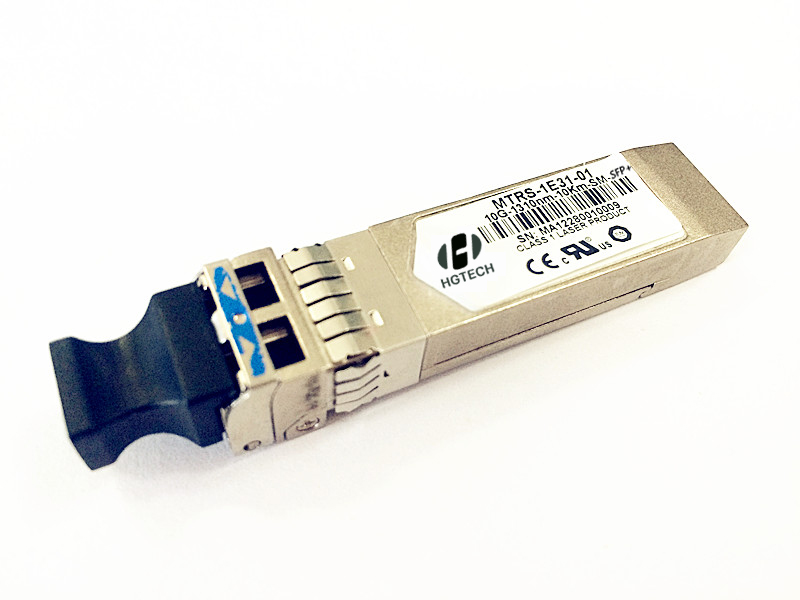
Description MTRS-1E31-01 is a high performance, cost effective modules, which is supporting Multi Rate4.9152Gbps to 10.3125Gbps, and transmission distance up to 10km on SM fiber. The transceiver consists of two sections: The transmitter section incorporates a laser driver and a 1310nm DFB laser. The receiver section consists of a PIN photodiode integrated with a transimpedance preamplifier (TIA) and a Limitting Amplifier. The module is hot pluggable into the 20-pin connector. The high-speed electrical interface is base on low voltage logic, with nominal 100 Ohms differential impedance and AC coupled in the module. The optical output can be disabled by LVTTL logic high-level input of TX_DIS. Transmit Fault (Tx_Fault) is provided to indicate that the module transmitter has detected a fault condition related to laser operation or safety. Loss of signal (RX_LOS) output is provided to indicate the loss of an input optical signal of receiver. A serial EEPROM in the transceiver allows the user to access transceiver monitoring and configuration data via the 2-wire SFP Management Interface. This interface uses a single address, A0h, with a memory map divided into a lower and upper area. Basic digital diagnostic (DD) data is held in the lower area while specific data is held in a series of tables in the high memory area. Features l Up to 10km transmission distance l Support Multi Rate 4.9152 Gbps to 10.3125 Gbps l 1310nm DFB Laser Transmitter and PIN Receiver l SFI electrical interface l 2-wire interface for integrated Digital Diagnostic monitoring l SFP+ MSA package with duplex LC connector l Hot pluggable l Very low EMI and excellent ESD protection l +3.3V power supply l Power consumption less than 1.0W l Operating case temperature: -40~+85°C Applications l High-speed storage area networks l Computer cluster cross-connect l Custom high-speed data pipes l LTE optical repeater application Compliance l Compliant with Fiber Channel(FC)-Standard INCITS 352 l Compliant with IEEE 802.3ae-2002 l Compliant with SFF-8431 Specification Absolute Maximum Ratings Parameter Symbol Min. Max. Unit Notes Storage Temperature TS -40 +85 ℃ Supply Voltage VCC3 -0.4 3.6 V Relative Humidity RH 5 +95 % Note1 Rx Input Average Power Pmax - +1.5 dBm Notes: [1] Non-condensing state. Recommended Operating Conditions Parameter Symbol Min. Typical Max. Unit Operating Case Temperature TC -40 25 +85 ℃ Power Supply Voltage VCC3 3.13 3.3 3.47 V ICC3 - - 300 mA Power Dissipation PD - - 1.0 W 4.9152 9.8304 10.3125 Gbps Transmission Distance - - 10 Km Transmitter Operating Characteristic-Optical, Electrical Parameter Symbol Min. Typical Max. Unit Note Center Wavelength λC 1260 1355 nm Spectral Width(-20dB) Pm - - 1 nm Side Mode Suppression Ratio SMSR 30 - dBm Laser Off Power Poff - - -30 dBm Average Optical Power Pavg -8.2 - 0.5 dBm Extinction Ratio ER 3.5 - - dB Transmitter Dispersion Penalty TDP - - 3.2 dB Relative Intensity Noise Rin - - -128 dB/Hz Optical Return Loss Tolerance - - 12 dB 4.9152 9.8304 10.3125 Gbps Optical Eye Mask 5 - - % Note1 Tx Input Diff. Voltage VI 180 450 700 mV Tx Fault VoL 0 - 0.8 At 0.7mA VoH 2 - 3.3 V Notes: [1] Eye Mask Margin(1000 consecutive snapshots at typical rate and room temperature) Receiver Operating Characteristic-Optical, Electrical Parameter Symbol Min. Typ. Max. Unit Note Center Wavelength λr 1260 - 1355 nm Receiver Sensitivity (Average Power) Psens - - -14.4 dBm Receiver Sensitivity (OMA) - - -12.6 dBm Los Assert LosA -30 - - dBm Los Dessert LosD - - -15 dBm Los Hysteresis LosH 0.5 - 6 dB Overload Pin 0.5 - - dBm Receive electrical 3dB upper cutoff frequency - - 12.3 GHz Receiver Reflectance - - -12 dB Operating Data Rate 4.9152 9.8304 10.3125 Gbps Rx Output Diff Voltage Vo 550 - 850 mV Parameter Symbol Min. Max. Unit DMI_Temp -3 3 ℃ Over operating temp Laser power monitor absolute error DMI_TX -2 2 dB RX power monitor absolute error DMI_RX -2 2 dB Supply voltage monitor absolute error DMI_VCC -0.1 0.1 V Bias current monitor absolute error DMI_Ibias -10% 10% mA
Control and Status I/O Timing Characteristics Parameter Symbol Min. Max. Unit Note TX Disable Assert Time t_off - 100 µs Note1 TX Disable Negate Time t_on - 2 ms Note2 Time to initialize including reset of TX_Fault t_init - 300 ms Note3 TX Fault Assert Time t_fault - 1 ms Note4 TX Disable to Reset t_reset 10 - µs Note5 LOS Assert Time t_loss_on - 100 µs Note6 LOS Deassert Time t_loss_off - 100 µs Note7 Serial ID Clock Rate f_serial_clock 100 400 kHz Notes: [1] Time from rising edge of TX Disable to when the optical output falls below 10% of nominal [2] Time from falling edge of TX Disable to when the modulated optical output rises above 90% of nominal [3] From power on or negation of TX Fault using TX Disable [4] Time from fault to TX fault on [5] Time TX Disable must be held high to reset TX_fault [6] Time from LOS state to RX LOS assert [7] Time from non-LOS state to RX LOS deassert.
Note
