
| 产品模块: | 10G SONET SFP+ LR Transceiver |
| 订购信息: | |
| 验证码: |
|
| 类 别: | 电子邮箱: | ||
| 电 话: | QQ: | ||
| *标题: | |||
| *留言内容: | |||
| *验证码: |
|
||
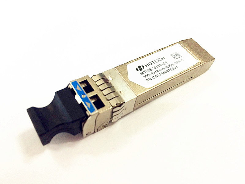
Description
The MTRS-2E30-01 is a very compact 10Gb/s optical transceiver module for serial optical communication applications at 10Gb/s. The MTRS-2E30-01 series converts a 10Gb/s serial electrical data stream to 10Gb/s optical output signal and a 10Gb/s optical input signal to 10Gb/s serial electrical data streams. The high speed 10Gb/s electrical interface is fully compliant with XFI specification (built in CDR on both TX and RX) and allows FR4 host PCB trace up to 200mm. The MTRS-2E30-01 is designed for use in a variety of
10Gb/s equipment SDH/SONET (9.95Gb/s), Ethernet LAN (10.3Gb/s) and FC (10.5Gb/s). The customer can adjust interface’ electrical level to select 8.5G~11.3G rate section. The high performance 1310nm DFB transmitter coupled with a high sensitivity PIN receiver provide superior performance for applications up to 10km with SMF. The fully compliant SFP form factor provides high density applications, hot plug ability easy optical port upgrades and low EMI emission.
The SFP+ LR w/CDR module electrical interface is compliant to XFI electrical specifications. The transmitter input and receiver output impedance is
100Ohms differential. Data lines are internally AC coupled. The module provides differential termination and reduce differential to common mode conversion for quality signal termination and low EMI. XFI typically operates over 200 mm of improved FR4 material or up to about 150mmof standard FR4 with one connector.
Features
l 10Gb/s serial optical interface
l 1310nm DFB transmitter, PIN photo-detector
l Transmission distance up to 10Km with SMF
l LC duplex conector
l Integrated clock and data recovery (CDR) function
l Operating case temperature:0°C~70°C
Applications
l SONET(OC-192)/SDH(STM64)
l 10GBASE-LR (10.3125Gbps)
l 10GBASE-LW (9.953Gbps)
Compliance
l Compliant with IEEE 802.3ae-2002 10G Base-LR
l Compliant with SFF-8431 & SFF-8083 & SFF-8432 & SFF-8472
l Compliant with RoHS
Specification
|
Table1-Absolute Maximum Ratings |
|||||
|
Parameter |
Symbol |
Min. |
Typical |
Max. |
Unit |
|
Storage Temperature |
Ts |
-40 |
- |
+85 |
℃ |
|
Operating Case Temperature |
Tc |
0 |
- |
+70 |
℃ |
|
Supply Voltage |
Vcc |
0 |
- |
3.6 |
V |
|
Relative Humidity |
RH |
5 |
- |
+95 |
% |
|
Rx Input Average Power |
Pmax |
- |
- |
+3 |
dBm |
|
Table2-Recommended Operating Conditions |
|||||
|
Parameter |
Symbol |
Min. |
Typical |
Max. |
Unit |
|
Operating Case Temperature |
TC |
0 |
25 |
+70 |
|
|
Power Supply Voltage |
VCC3 |
3.14 |
3.3 |
3.46 |
V |
|
Power Supply Current |
ICC3 |
- |
- |
430 |
mA |
|
Power Consumption |
|
- |
- |
1500 |
mW |
|
Table3-Transmitter Operating Characteristic-Optical, Electrical |
||||||
|
Parameter |
Symbol |
Min. |
Typical |
Max. |
Unit |
Note |
|
Operating Data Rate |
DR |
8.5 |
9.953 |
11.3 |
Gb/s |
1 |
|
Output Center Wavelength |
λ c |
1290 |
1310 |
1330 |
nm |
|
|
Spectral Width |
⊿λ |
- |
- |
1 |
nm |
|
|
Side Mode Suppression Ratio |
SMSR |
30 |
- |
- |
dB |
|
|
Average Output Power |
Po |
-6 |
- |
-1 |
dBm |
2 |
|
Disabled Power |
Poff |
- |
- |
-30 |
dBm |
2 |
|
Extinction Ratio |
ER |
6 |
- |
- |
dB |
2 |
|
Minimum OMA-TDP (10G Ethernet) |
OMAtdp |
-5.2 |
- |
- |
dBm |
3 |
|
Eye Mask (@SONET/SDH) |
GR-253-CORE/ITU-T G.691 |
|
2 |
|||
|
Eye Mask (@10G Ethernet) |
IEEE802.3ae |
|
3 |
|||
|
Generation Jitter 1 (20kHz - 80MHz) |
- |
- |
- |
0.3 |
UIp-p |
2,4 |
|
Generation Jitter 2 (4MHz - 80MHz) |
- |
- |
- |
0.1 |
UIp-p |
2,4 |
|
Relative Intensity Noise |
RIN |
- |
- |
-128 |
dB/Hz |
|
|
Chromatic Dispersion (SONET/SDH) |
CD |
- |
- |
6.6 |
ps/nm |
|
|
Operating Distance |
- |
- |
- |
10 |
km |
|
|
Attenuation (SONET/SDH) |
- |
0 |
- |
4 |
dB |
|
|
Channel Insertion Loss (10G Ethernet) |
- |
0 |
- |
6 |
dB |
|
|
Maximum DGD (SONET/SDH) |
DGD |
- |
- |
30 |
ps |
|
|
Single Ended Output Voltage Tolerance |
- |
-0.3 |
- |
4 |
V |
|
|
Common mode voltage tolerance |
- |
15 |
- |
- |
mV |
|
|
Tx Input Diff Voltage |
VI |
120 |
- |
820 |
mV |
|
|
Tx Fault |
Vol |
-0.3 |
- |
0.4 |
V |
At 0.7mA |
|
Data Dependent Input Jitter |
DDJ |
- |
- |
0.1 |
UI |
|
|
Data Input Total Jitter |
TJ |
- |
- |
0.28 |
UI |
|
|
Table4-Receiver Operating Characteristic-Optical, Electrical |
||||||
|
Parameter |
Symbol |
Min. |
Typical |
Max. |
Unit |
Note |
|
Operating Data Rate |
- |
8.5 |
9.953 |
11.3 |
Gb/s |
1 |
|
Input Center Wavelength |
lrc |
1260 |
|
1620 |
nm |
|
|
Overload |
Rovl |
0.5 |
- |
- |
dBm |
|
|
Minimum Sensitivity |
Rsen |
- |
- |
-14.4 |
dBm |
2 |
|
Sensitivity in OMA |
OMA0 |
- |
- |
-12.6 |
dBm |
3 |
|
Stressed Sensitivity in OMA |
OMAst |
- |
- |
-10.3 |
dBm |
3 |
|
RX_LOS Assert |
RLOSa |
-30 |
- |
- |
dBm |
|
|
RX_LOS Deassert |
RLOSd |
- |
- |
-16 |
dBm |
|
|
RX_LOS Hysteresis |
RLOSh |
0.5 |
- |
5 |
dB |
|
|
Optical Path Penalty |
DP |
- |
- |
1 |
dB |
1 |
|
Optical Return Loss |
ORL |
|
- |
-14 |
dB |
|
|
Jitter Tolerance |
GR-253-CORE/ITU-T G.783 |
|
|
|||
|
Single Ended Output Voltage Tolerance |
- |
-0.3 |
- |
4 |
V |
|
|
Rx Output Diff Voltage |
Vo |
340 |
- |
850 |
mV |
|
|
Data output rise/fall time |
|
30 |
|
|
ps |
20%~80% |
|
Total Jitter |
TJ |
- |
- |
0.7 |
UI |
|
|
Deterministic Jitter |
DJ |
- |
- |
0.42 |
UI |
|
Notes:
[1]Data rate tolerance 10GBASE-LR/LW: typ.+/-100ppm
[2]Measured at 9.953Gbps,Non-framed PRBS2^31-1,NRZ
[3]Measured by using SFP+ evaluation board.
|
Table5-Control and Status I/O Timing Characteristics |
||||||
|
Parameter |
Symbol |
Min. |
Typical |
Max. |
Unit |
Note |
|
TX Disable Assert Time |
t_off |
|
- |
10 |
µs |
1 |
|
TX Disable Negate Time |
t_on |
|
- |
1 |
ms |
2 |
|
Time to initialize including reset of TX_Fault |
t_init |
|
- |
300 |
ms |
3 |
|
TX Fault Assert Time |
t_fault |
|
- |
100 |
µs |
4 |
|
TX Disable to Reset |
t_reset |
10 |
- |
|
µs |
5 |
|
LOS Assert Time |
t_loss_on |
|
- |
100 |
µs |
6 |
|
LOS Deassert Time |
t_loss_off |
|
- |
100 |
µs |
7 |
|
Rate-Select Change Time |
t_ratesel |
|
- |
10 |
µs |
8 |
|
Serial ID Clock Rate |
f_serial_clock |
|
- |
100 |
kHz |
|
Notes:
[1] Time from rising edge of TX Disable to when the optical output falls below 10% of nominal
[2] Time from falling edge of TX Disable to when the modulated optical output rises above 90% of nominal
[3] From power on or negation of TX Fault using TX Disable
[4] Time from fault to TX fault on
[5] Time TX Disable must be held high to reset TX_fault
[6] Time from LOS state to RX LOS assert
[7] Time from non-LOS state to RX LOS deassert.
[8] Time from rising or falling edge of Rate Select input until receiver bandwidth is in conformance with appropriate specification
Digital Diagnostic Function
The following digital diagnostic characteristics are defined over the Recommended Operating Environment unless otherwise specified. It is compliant to SFF-8472 Rev11.1 with internal calibration mode. For external calibration mode
please contact our sales stuff.
Table6: Digital diagnostic specification table
|
Parameter |
Symbol |
Min. |
Max |
Unit |
Notes |
|
Temperature monitor absolute error |
DMI_Temp |
-3 |
3 |
degC |
|
|
Laser power monitor absolute error |
DMI_TX |
-3 |
3 |
dB |
|
|
RX power monitor absolute error |
DMI_RX |
-3 |
3 |
dB |
|
|
Supply voltage monitor absolute error |
DMI_VCC |
-3% |
-3% |
V |
|
|
Bias current monitor |
DMI_Ibias |
-10% |
10% |
mA |
|


