
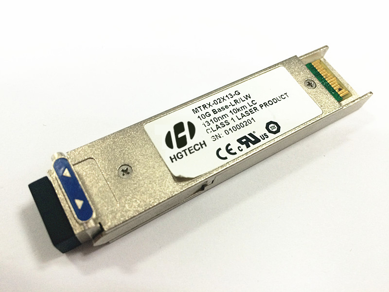
| 产品模块: | 10G XFP LR Transceiver |
| 订购信息: | |
| 验证码: |
|
| 类 别: | 电子邮箱: | ||
| 电 话: | QQ: | ||
| *标题: | |||
| *留言内容: | |||
| *验证码: |
|
||
Description
MTRX-02X13-G is a high performance, cost effective modules, which is optimized for
The transceiver consists of two sections: The transmitter section incorporates a 1310nm uncooled DML, driver and CDR. The receiver section consists of a PIN photodiode integrated with a transimpedance preamplifier (TIA) , LA and CDR. The module is hot pluggable into the 30-pin connector. The high-speed electrical interface is base on low voltage logic, with nominal 100 Ohms differential impedance and AC coupled in the module. The optical output can be disabled by LVTTL logic high-level input of TX_DIS. Loss of signal (RX_LOS) output is provided to indicate the loss of an input optical signal of receiver.
A serial EEPROM in the transceiver allows the user to access transceiver monitoring and configuration data via the 2-wire XFP Management Interface. This interface uses a single address, A0h, with a memory map divided into a lower and upper area. Basic digital diagnostic (DD) data is held in the lower area while specific data is held in a series of tables in the high memory area.
Features
l Support 10GE application at the data-rate of 9.953Gbps to 11.1Gbps
l Up to
l 1310nm uncooled DML and PIN receiver
l XFI electrical interface
l 2-wire interface for integrated Digital Diagnostic monitoring
l XFP MSA package with duplex LC connector
l Hot pluggable
l Very low EMI and excellent ESD protection
l +3.3V power supply
l Power consumption less than 2 W
l Operating Case Temprature:0~+
Application
l SONET(OC-192)/SDH(STM64) line card
l 10GBASE-LR at 10.3125Gbps
l 10GBASE-LW at 9.953Gbps
l 10GE Ethernet switches and routers
Standard
l Compliant with SFF-INF-8077i
l RoHS compliance
l GR-468-CORE
l MIL-STD-883
Specification
|
Absolute Maximum Ratings |
||||
|
Parameter |
Symbol |
Min. |
Max. |
Unit |
|
Storage Temperature |
TS |
-40 |
+85 |
℃ |
|
Supply Voltage |
VCC3 |
-0.5 |
3.6 |
V |
|
Relative Humidity |
RH |
-5 |
+95 |
% |
|
RX Input Average Power |
Pmax |
- |
0 |
dBm |
|
Recommended Operating Conditions |
|||||
|
Parameter |
Symbol |
Min. |
Typical |
Max. |
Unit |
|
Operating Case Temperature |
TC |
0 |
- |
+70 |
℃ |
|
Power Supply Voltage |
VCC3 |
3.135 |
3.3 |
3.475 |
V |
|
Power Supply Current |
ICC3 |
- |
- |
575 |
mA |
|
Power Dissipation |
PD |
- |
- |
2 |
W |
|
Data Rate |
|
9.953 |
- |
11.1 |
Gbps |
|
Transmission Distance |
|
- |
|
10 |
Km |
Transmitter Operating Characteristic-Optical |
||||||
|
Parameter |
Symbol |
Min. |
Typical |
Max. |
Unit |
Note
|
|
Center Wavelength |
λC |
1290 |
1310 |
1330 |
nm |
Note1 |
|
Spectral Width(-20dB) |
Pm |
- |
- |
1 |
nm |
|
|
Side Mode Suppression Ratio |
SMSR |
30 |
- |
- |
dB |
|
|
Laser Off Power |
Poff |
- |
- |
-30 |
dBm |
|
|
Average Optical Power |
Pavg |
-6 |
- |
-1 |
dBm |
Note1 |
|
Extinction Ratio |
ER |
6 |
- |
- |
dB |
|
|
Transmitter and Dispersion Penalty |
TDP |
- |
- |
1 |
dB |
|
|
Relative Intensity Noise |
Rin |
- |
- |
-128 |
dB/Hz |
|
|
Operating Data Rate |
|
9.953 |
- |
11.1 |
Gbps |
|
|
Optical Eye Mask |
5% |
|
||||
Notes:
[1] Average optical power shall be measured using the methods specified in TIA/EIA-455-95.
|
Receiver Operating Characteristic-Optical |
||||||
|
Parameter |
Symbol |
Min. |
Typical |
Max. |
Unit |
Note
|
|
Center Wavelength |
λr |
1270 |
|
1600 |
nm |
|
|
Receiver Sensitivity (Average Power) |
Psens |
- |
|
-14.4 |
dBm |
Note1 |
|
Stressed Sensitivity |
|
- |
- |
-10.3 |
dBm |
Note1 |
|
Los Assert |
LosA |
-32 |
- |
- |
dBm |
|
|
Los Dessert |
LosD |
- |
- |
-15.4 |
dBm |
|
|
Los Hysteresis |
LosH |
0.5 |
- |
6 |
dB |
|
|
Overload |
Pin |
0.5 |
- |
- |
dBm |
|
|
Optical Return Loss |
ORL |
|
|
14 |
dB |
|
|
Receiver reflectance |
Rr |
|
|
-14 |
dB |
|
|
Operating Data Rate |
|
9.953 |
- |
11.1 |
Gbps |
|
|
Sensitivity in OMA |
|
|
|
-12.6 |
dBm |
|
|
Max Input power |
|
0.5 |
- |
- |
dBm |
|
Notes:
[1] Receiver sensitivity is informative. Stressed receiver sensitivity shall be measured with conformance test signal for BER =1x 10-12 .
|
Low Speed Control and Alarm Signals Electrical Interface |
|||||
|
Parameter |
Symbol |
Min |
Max |
Units |
Note |
|
Differential data input swing |
Vin |
120 |
820 |
mVpp |
|
|
Differential data output swing |
Vout |
340 |
850 |
mVpp |
|
|
XFP Interrupt, Mod_NR, RX_LOS |
Vol |
0.0 |
0.4 |
V |
Note1 |
|
Voh |
VCC3-0.5 |
VCC3+0.3 |
Note2 |
||
|
XFP TX_DIS, P_DOWN/RST |
Vil |
-0.3 |
0.8 |
V |
Note3 |
|
Vih |
2.0 |
VCC3+0.3 |
Note4 |
||
|
XFP SCL and SDA Output |
Vol |
0.0 |
0.4 |
V |
Note1 |
|
Voh |
VCC3-0.5 |
VCC3+0.3 |
Note2 |
||
|
XFP SCL and SDA Input |
Vil |
-0.3 |
VCC3*0.3 |
V |
Note5 |
|
Vih |
VCC3*0.7 |
VCC3+0.5 |
Note6 |
||
|
Capacitance for XFP SCL and SDA I/O pin |
Ci |
- |
14 |
Pf |
|
|
Total bus capacitive load for SCL and SDA |
Cb |
- |
100 |
Pf |
Note7 |
|
- |
400 |
Pf |
Note8 |
||
Notes:
[1] Pull-up resistor must be connected to host_Vcc on the host board. Iol(max)=3mA
[2] Pull-up resistor must be connected to host_Vcc on the host board.
[3] Pull-up resistor connected to VCC3 within XFP module. Iil(max)= -10 uA
[4] Pull-up resistor connected to VCC3 within XFP module. Iih(max)= 10 uA
[5] Pull-up resistor must be connected to host_Vcc on the host board. Iol(max)= -10 uA
[6] Pull-up resistor must be connected to host_Vcc on the host board. Iol(max)= 10 uA.
[7] At 400KHz, 3.0kohms, at 100kHz 8.0kohms max.
[8] At 400KHz, 0.8kohms, at 100kHz 2.0kohms max.


